
RF (Radio Frequency) Cables Explained: A Guide to Types and Industrial Applications
In commercial radio systems, the cable is not just a peripheral accessory. It is a critical engineering component that determines whether a signal reaches its destination or fails within the copper conductor. If you have struggled with signal dropouts in remote New Zealand terrain or felt overwhelmed by jargon like impedance and attenuation, you aren't alone.
In commercial radio systems, the cable is not just a peripheral accessory. It is a critical engineering component that determines whether a signal reaches its destination or fails within the copper conductor. If you have struggled with signal dropouts in remote New Zealand terrain or felt overwhelmed by jargon like impedance and attenuation, you aren't alone. This guide to RF (Radio Frequency) Cables Explained: Types provides the technical clarity needed to avoid costly system failures.
Selecting high-quality components is essential for long-term reliability in harsh environments. We will explore the technical specifications and industrial applications for various cable formats. This includes those compliant with the latest EN IEC 60966-4-4:2026 standards for high-frequency applications and the April 2026 updates to IEC 61196-1-326 regarding mechanical reliability and clamp testing.
You will learn how to identify the correct cable for UHF/VHF or satellite systems and understand the trade-offs between initial cost and performance. This article outlines the selection criteria for ensuring your communication infrastructure remains robust, highlighting why Mobile Systems Limited is the trusted choice for professional installations across New Zealand. Understanding these variables ensures your system remains compliant with modern safety and environmental regulations like RoHS 3.
Key Takeaways
- Understand how the internal construction of a coaxial cable, including the dielectric insulator and center conductor, directly impacts signal integrity and prevents interference.
- Distinguish between common cable grades like RG-58 and RG-213 by reviewing the technical specifications in this guide to RF (Radio Frequency) Cables Explained: Types.
- Learn to select the correct connector interfaces, such as N-Type or SMA, while matching frequency ratings to your specific hardware for optimal performance.
- Discover why professional SWR testing and precise termination are critical to preventing costly transmitter failures and maintaining system reliability in demanding New Zealand conditions.
Understanding the Role of RF Cables in Modern Communication
Radio Frequency (RF) cables are specialized transmission lines engineered to carry high-frequency signals while maintaining minimal signal loss. This guide to RF (Radio Frequency) Cables Explained: Types focuses on how these components function as the vital link between your transceiver and antenna. Unlike standard electrical wiring, these cables are designed to manage electromagnetic fields within the cable structure itself. This prevents external interference and internal signal leakage that would otherwise degrade communication quality.
Choosing the wrong cable often results in reduced operational range, persistent static, or complete hardware failure during critical moments. In a commercial environment, the cable isn't just a wire; it's a precision-engineered component that must match the specific frequency of your system. If the cable cannot handle the power output or frequency of the radio, the energy reflects back into the transmitter, potentially causing permanent damage.
To better understand the variety of connectors used with these cables, watch this overview:
The Difference Between RF and Standard Cables
Standard power cables are designed for low-frequency electricity and lack the concept of controlled impedance. RF cables, however, rely on specific physical dimensions between the core and the shield to ensure the signal flows efficiently. You can explore the technical details in The Anatomy and Physics of an RF Coaxial Cable, which details how the dielectric layer maintains this impedance. High-quality shielding is also essential because it blocks electronic noise from other machinery on-site. Consumer-grade cables often utilize thin braiding that fails in industrial NZ environments, leading to signal dropouts when you need connectivity most.
Why Quality Cabling Matters for NZ Businesses
Reliability is a non-negotiable requirement for New Zealand's remote sectors. Whether operating in rugged forestry blocks or demanding maritime environments, your equipment must withstand physical stress and environmental exposure. Using high-quality cabling protects expensive assets like Tait radios from damage caused by high Standing Wave Ratios (SWR). We advocate for system integrity, where every connector and cable length is matched to the specific hardware in use. A single weak link can compromise an entire fleet tracking system or emergency radio network. Investing in industrial-grade components prevents the need for frequent, costly site visits to repair failed connections.
The Anatomy and Physics of an RF Coaxial Cable
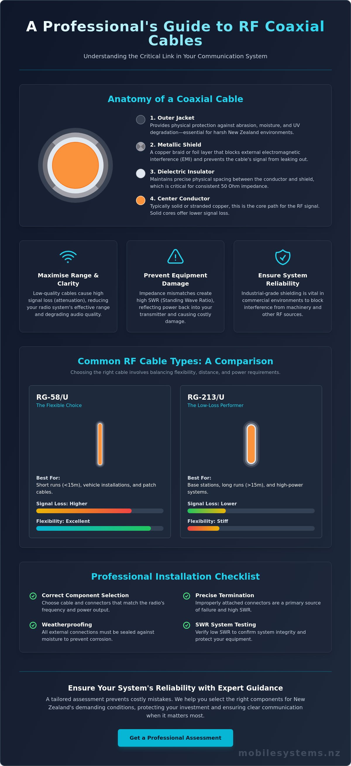
The physical construction of a coaxial cable determines its electrical properties and suitability for different environments. This breakdown of RF (Radio Frequency) Cables Explained: Types focuses on the four primary layers that constitute a professional-grade cable. Each layer must be manufactured to precise tolerances to ensure the signal remains intact from the radio to the antenna.
The centre conductor serves as the primary path for the signal. It's typically made from solid or stranded copper. Solid cores offer lower signal loss over long distances, while stranded versions provide the flexibility required for vehicle-mounted radio installations. Surrounding the core is the dielectric insulator, a layer that maintains the precise spacing between the core and the shield. This spacing is critical for maintaining consistent impedance throughout the cable run.
The outer shield, usually comprised of a copper braid or aluminium foil, protects the signal from external electromagnetic interference. It also keeps the radio frequency energy contained within the cable to prevent leakage. Finally, the outer jacket provides protection against physical abrasion. For New Zealand applications, this jacket must be rated to withstand high UV levels to prevent cracking and moisture ingress in our harsh sunlight.
Understanding Impedance: 50 Ohm vs 75 Ohm
In the world of commercial radio and wireless data, 50 Ohm is the universal industry standard. This specific impedance level provides the best balance between power handling and low signal loss for transceivers and vehicle-mounted two-way radios. By contrast, 75 Ohm cables are typically reserved for video signals and television infrastructure.
Using a 75 Ohm cable for a two-way radio system creates an "impedance mismatch." This error causes energy to reflect back into the radio instead of reaching the antenna. These reflections generate excessive heat and can eventually burn out the radio's transmitter. Consult a comprehensive guide to RF cables to verify the specifications of your components before beginning an installation.
Signal Attenuation and Loss
Attenuation refers to the gradual reduction in signal strength as it travels through the cable. This loss is measured in decibels (dB) per unit of distance. Higher frequencies, like those used in UHF or satellite systems, suffer from significantly more attenuation than lower VHF frequencies. This means a cable that works for a marine radio might be entirely unsuitable for a high-speed data link.
Choosing a cable with a lower loss rating is essential for long runs or high-frequency applications. If you're unsure which grade fits your specific terrain, a professional assessment of your system design often prevents performance bottlenecks and ensures long-term reliability.
Common RF Cable Types and Their Industrial Uses
Selecting the correct cable requires balancing physical flexibility with electrical performance. This overview of RF (Radio Frequency) Cables Explained: Types focuses on the most common standards used in New Zealand industrial applications. Each cable type serves a specific purpose, from mobile fleet management to high-altitude repeater stations.
- RG-58: This is the industry standard "workhorse" for short-run installations. Its small diameter makes it ideal for vehicle-mounted antennas where routing through narrow gaps is necessary.
- RG-213: A thicker alternative to the RG-58, this cable offers significantly lower loss. It's often used in marine environments or for base stations where cable runs are longer.
- LMR-400: This high-performance, low-loss cable is the preferred choice for UHF and high-frequency digital systems. It maintains signal strength over distances where standard cables would fail.
- Low-Loss 195/240: These modern cables provide a compromise between the small size of RG-58 and the performance of larger cables. They are increasingly used for critical data links and cellular boosters.
Cabling for Vehicle-Mounted Two-Way Radios
Vehicle installations demand cables that can withstand constant vibration and tight routing through chassis and interior trim. RG-58 is the primary choice for these applications because it's flexible enough to navigate small entry points without kinking. While it has higher loss than thicker cables, the short distances involved in a vehicle setup mean the impact on signal quality is negligible.
Many professional users interface their handheld radios with external vehicle antennas to boost range. In these scenarios, using a high-quality RG-58 lead ensures the signal reaches the roof-mounted antenna without significant degradation. It's vital to use industrial-grade shielding to prevent interference from the vehicle's own electronic control units (ECUs).
Fixed Base Stations and Remote Repeaters
Base stations and remote repeaters often require antenna placement high on masts or building roofs. When cable runs exceed 20 metres, signal loss becomes a major factor. In these cases, LMR-400 or even larger "heliax" cables are necessary. These thicker cables use a solid core and superior dielectric materials to ensure the maximum amount of power reaches the antenna.
Low-loss cabling is also critical for modern satellite backhaul systems. If you're utilizing Starlink or other satellite services for remote connectivity, the cable connecting the outdoor unit to your network must handle high-frequency data without error. Using a standard, high-loss cable for these systems will result in reduced bandwidth and increased latency. A tailored assessment of your site's physical layout often prevents these performance bottlenecks before they occur.
Selection Criteria: Connectors, Loss, and Environment
Selecting the right hardware goes beyond matching a cable to a radio. This guide to RF (Radio Frequency) Cables Explained: Types identifies the mechanical and environmental factors that determine long-term system health. If you overlook these variables, even the most expensive transceiver will underperform due to signal leakage or physical degradation.
To ensure a reliable installation, you must evaluate four primary criteria:
- Connector Compatibility: Matching the physical interface of your radios, antennas, and boosters.
- Frequency Rating: Verifying the cable can handle the specific VHF, UHF, or GHz band without excessive loss.
- Environmental Resilience: Selecting materials that withstand New Zealand's high UV levels and salt air.
- Physical Flexibility: Balancing the need for low-loss performance with the flexibility required for vehicle routing.
Choosing the Correct RF Connector
Connectors are the primary point of failure in many communication systems. The N-Type connector is the gold standard for commercial outdoor installations because it's robust and inherently waterproof when properly tightened. For portable devices or internal chassis connections, SMA and BNC connectors are more common due to their smaller footprint and secure locking mechanisms.
You should avoid using low-quality adapters to bridge different connector types whenever possible. Each adapter introduces a measurable "insertion loss" that weakens your signal. If your hardware requires multiple transitions, it's often more efficient to have a custom cable assembly made with the correct terminations already in place.
Durability in the New Zealand Environment
New Zealand's environmental conditions are particularly aggressive toward electronic components. High UV exposure causes standard PVC jackets to become brittle and crack within a few years. Once the jacket fails, moisture enters the cable through a process called wicking. This is where water travels along the copper braid, corroding the conductor and ruining the entire cable run.
In coastal areas, salt-heavy air accelerates the oxidation of copper. We recommend cables with polyethylene (PE) jackets or tinned copper braids for these locations to extend the system's lifespan. This level of protection is especially critical for marine communication setups where IP-rated seals and moisture-resistant materials are a requirement. Ensuring your system is properly weatherized requires specialized knowledge of local conditions. For a technical review of your component selection, contact Mobile Systems Limited to prevent costly environmental failures.
Professional Installation and System Integration
Even with the correct specifications, the reliability of a communication system depends on the quality of the physical installation. This guide to RF (Radio Frequency) Cables Explained: Types highlights that high-performance components require precise integration to function as intended. Amateur or "DIY" termination often leads to catastrophic hardware failure, specifically when a single stray strand of shielding braid touches the center conductor, creating a short circuit that can destroy a radio's power amplifier.
Professional installers prioritize Standing Wave Ratio (SWR) testing once the cable and antenna are in place. This test measures how much energy is being reflected back to the radio versus how much is being transmitted. A high SWR indicates an impedance mismatch or a faulty connection, which must be rectified before the system is put into service. Ignoring this metric can lead to poor range and permanent hardware damage.
Cable routing also plays a major role in longevity. Every cable has a minimum bend radius; exceeding this can deform the dielectric insulator and change the cable's impedance. In vehicle-mounted setups, cables must be kept away from high-heat sources like exhaust manifolds or engine blocks, which can melt the outer jacket and lead to immediate signal failure. Using proper mounting hardware prevents the cable from rubbing against sharp metal edges during vehicle operation.
The Value of Specialised Tooling
Achieving a gas-tight seal on an RF connector requires professional-grade crimping tools rather than generic pliers or hand-soldering. Mobile Systems Limited utilizes calibrated tooling to ensure every connection meets industrial standards. These tools provide consistent pressure that prevents the connector from pulling off under physical stress or vibration. Hand-soldered connections are often brittle and prone to cracking in high-vibration environments like trucking or marine use.
We use advanced cable and antenna analyzers to verify performance across the entire frequency range after installation. These devices can pinpoint the exact location of a fault within a cable run, saving hours of manual troubleshooting. Professionally finished connections are also sealed with adhesive-lined heat-shrink tubing. This provides a secondary barrier against moisture ingress, which is a primary cause of performance degradation in New Zealand's humid and coastal climates.
Partnering with Mobile Systems for Your Fleet
Mobile Systems Limited has extensive experience designing and installing robust communication networks for New Zealand’s most demanding industries. From forestry blocks to commercial marine fleets, we understand the specific challenges posed by rugged terrain and environmental exposure. Our team ensures that your vehicle-mounted two-way radios and satellite systems are integrated with the highest level of technical precision to maintain system integrity.
Our mobile support vehicles are equipped to provide on-site technical assistance nationwide, ensuring your fleet stays connected without unnecessary downtime. A tailored assessment often prevents costly mistakes in commercial deployments. If you require a comprehensive audit of your current communication infrastructure or a new installation, contact our team to discuss a professional solution for your business.
Ensuring Long-Term Reliability for Your Radio Network
Selecting the right transmission line is more than a technical detail; it's a strategic decision that affects the lifespan of your hardware. By understanding the specifications in this guide to RF (Radio Frequency) Cables Explained: Types, you can avoid signal dropouts and costly transmitter damage. Proper impedance matching and environmental protection are essential for maintaining connectivity in New Zealand's rugged terrain.
Professional installation remains the most effective way to guarantee performance. Mobile Systems Limited brings over 30 years of New Zealand communication expertise to every project. As an official Tait Communications authorised partner, we provide the technical precision required for complex fleet deployments. Our mobile support vehicles offer on-site servicing to ensure your systems remain operational in the field.
Don't leave your critical communications to chance. Consult with our specialists for a reliable communication system assessment to identify the best components for your specific operational needs. We look forward to helping you build a more resilient network.
Frequently Asked Questions
What is the most common type of RF cable for two-way radios?
RG-58 is the standard choice for short-run vehicle installations due to its flexibility. For fixed base stations with longer cable runs, LMR-400 is the preferred option because of its lower signal loss. The choice depends entirely on the balance between physical routing needs and the required electrical performance. This guide to RF (Radio Frequency) Cables Explained: Types helps you identify which grade prevents performance bottlenecks in your commercial radio fleet.
Can I use a TV coaxial cable for my UHF radio?
You shouldn't use TV coaxial cable because it has a 75 Ohm impedance. Commercial two-way radios and wireless data systems are designed for 50 Ohm impedance. Using 75 Ohm cable causes a significant impedance mismatch. This reflects power back into the transmitter, which can lead to overheating and permanent hardware failure. Always verify the impedance rating before connecting any hardware to ensure system safety and long-term reliability.
How long can an RF cable be before I lose signal?
Signal loss depends on the cable grade and the operating frequency. A standard RG-58 cable might be effective up to 5 or 10 metres for VHF radios. However, high-frequency UHF or digital systems will experience noticeable loss over the same distance. For runs exceeding 15 metres, moving to a lower-loss cable like LMR-400 is necessary to maintain signal integrity and range in demanding New Zealand terrain.
What is the difference between RG-58 and LMR-400?
The primary differences are physical diameter and signal attenuation. RG-58 is a thin, flexible cable with a diameter of approximately 5mm, making it easy to route through vehicle interiors. LMR-400 is much thicker at roughly 10mm and is significantly stiffer. While LMR-400 is more difficult to install, it is a key part of RF (Radio Frequency) Cables Explained: Types for those needing low signal loss over long distances.
Why does my radio cable get hot when I transmit?
Excessive heat during transmission usually indicates a high Standing Wave Ratio (SWR). This happens when the antenna and cable aren't properly matched, causing radio frequency energy to reflect back into the cable instead of being radiated. It can also occur if the cable's power rating is too low for the transmitter's output. Immediate testing with a professional analyser is required to prevent transmitter burnout and ensure your hardware remains operational.
Do I need to replace my RF cables if the outer jacket is cracked?
You must replace the cable immediately if the jacket is cracked. A compromised jacket allows moisture to enter the cable, which then travels along the braid through a process called wicking. This moisture corrodes the copper shield and changes the electrical properties of the dielectric insulator. Once water enters an RF cable, its performance is permanently degraded and it can no longer provide the reliable communication required for commercial operations.
What is the best way to waterproof an outdoor RF connection?
The most effective method is using self-amalgamating tape covered by a layer of high-quality electrical tape or adhesive-lined heat shrink. These materials create a gas-tight, waterproof seal that prevents moisture and salt air from entering the connector. In New Zealand's coastal environments, this protection is critical for preventing oxidation. Standard electrical tape alone is insufficient as it degrades quickly under high UV exposure and allows moisture ingress over time.
Can I join two RF cables together with an adapter?
You can join cables using a barrel adapter, but it isn't recommended for high-performance systems. Every adapter and connector pair introduces "insertion loss," which measurably weakens the signal. In a professional environment, it's always better to use a single, continuous cable run of the correct length. If you must use a joiner, ensure it matches the 50 Ohm impedance of your system to minimize reflections and prevent damage to your transmitter.
Related posts

- June 18, 2026
Mobile Systems Limited explains how digital radio repeaters work, why they're essential for overcoming New Zealand's terrain, and what RSM...

- May 27, 2026
Searching for Freedom Internet NZ? Here's the difference between the apartment ISP brand and genuine connectivity freedom for a mobile...

- May 25, 2026
Fixed, portable or marine? A straight guide to choosing the right satellite system for your NZ site, and why installation...